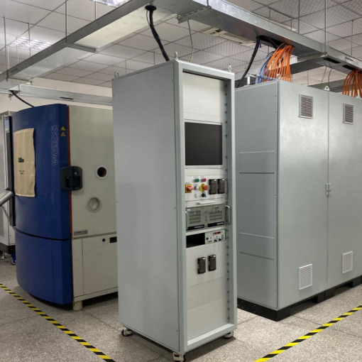
New energy power electroniccontroller endurance test bench
2024/3/13
![]()
Test Products
The equipment is used to test the lifespan of the core energy conversion components in new energy vehicles, including the on-board charger for charging batteries, the DC/DC for converting high-voltage and low-voltage batteries to each other, and the motor controller for driving motors.
Vehicle Charger(OBC)
DC Converter(DC/DC)
Motor Controller(PEU)
Converts AC power (220VAC) provided by the charging post into high voltage DC to charge high voltage batteries
High-voltage batteries and low-voltage batteries convert energy to each other.
Converts the energy from the high-voltage battery to the drive motor, providing power for the entire vehicle.
![]()
![]()
![]()
Life test theory
![]()
Product Driving Principle
Power electronic controller by the central controller MCU through the gate-level drive circuit, control IGBT array inverter, so as to achieve the purpose of driving the motor or energy conversion.
![]()
The core power device of the power electronic controller is a module composed of multiple IGBTs, and the life of this component directly determines the life of the product. A large number of tests have proved that the main form of failure of IGBT is thermal failure, i.e., the accumulated damage of IGBT temperature drives the product failure.
The main method of assessment is in extreme operating temperature conditions, the controller works under high load, so that the IGBT reaches the target assessment temperature, and lasts long enough to test time.
Test bench working principle
![]()
Simultaneously and accurately simulate the natural environment, working conditions and current load of the product, and test various controllers under high-power operating conditions.
Sample work simulation and realization
- Sample environment: all products are placed in the ambient temperature box for environmental simulation, connecting harnesses and cooling water through the wall of the temperature box;
- Cooling Cycle: A coolant temperature control unit is used to control the temperature and flow of cooling water to the sample;
- High-voltage battery: a high-voltage power supply is used to simulate battery discharge and a high-voltage electronic load to simulate battery charging;
- Motors: a reactor is used as a dummy load to simulate the characteristics of a motor;
- Low-voltage battery: the electronic load simulates the process of charging a low-voltage battery, and the battery power supply function is completed by the low-voltage power supply;
- Controller command transmitting and receiving: simulated by CAN card.
System integration and security
- PC-based instrument communication system, command distribution execution system, data acquisition and recording system;
- PLC as auxiliary I/O control and safety control;
- Tight stop system and hardware protection system composed of safety relays.
Testing Capability
Environment simulation
- Testing stations: 6
- Ambient temperature: -40 ~ 150 ℃
- Temperature rise and fall rate: 15 K/min (no load, the whole average)
- Cooling water temperature: -40 ~ 95 °C
- Cooling water flow rate: 1 ~ 15 L/min (per channel)
On-Board Charger (OBC)
- Input Voltage Range: 170 ~ 265 VAC (single phase) 290 ~ 460 VAC (three phase)
- Maximum input current (single sample): 40 A
- Output Voltage Range: 40 ~ 800 VDC
- Maximum output power (single sample): 10.5 kW
- Output Method: CC/CV/CR
- Reverse operation test: 3 forward + 3 reverse test (customer product tie-in required)
Direct Current Converter (DC/DC)
- Input Voltage Range: 20 ~ 1500 VDC
- Maximum Input Current (Single Sample): 40 A
- Output Voltage Range: 5 ~ 54 VDC
- Maximum output power (single sample): 5.76 kW
- Output Method: CC/CV/CR
Motor Controller (PEU)
- Input Voltage Range: 20 ~ 1500 VDC
- Maximum input current (single sample): 40 A
- Maximum output voltage (single sample): 750 V RMS
- Maximum output current (single sample): 300 A RMS (continuous) 680 A RMS (continuous for 10s)
Core Components
|
⚫ Environmental Simulation
|
|
|
⚫ Voltage power supply
|
|
|
⚫ High Voltage Electronic Load
|
|
|
⚫ Low Voltage Electronic Load
|
|
|
⚫ Chiller
|
|
|
⚫ AC Power Supply
|
|
|
⚫ Reactor
|
|
|
⚫ Control system
|
|
|
⚫ Data Acquisition
|
|
Functional configuration list
![]()
Software Architecture
Development Tools
Labview, the leader in development software for the test field
Module distribution and data association
Developed based on the endurance test platform, each module shares the same data and control bus, and works together to meet all mainstream endurance test requirements.
State Machines and Servers
The application of state machines and servers makes the architecture clear, facilitates the completion of additional functionality extensions, and improves code reuse.
![]()
User Interface
User Management
MD5 encrypted user password saving![]()
Real-time data display
Real-time data of all channels, protection upper and lower limit value display interface .
Device Alarm Information
Keep a record of device alarms to assist in investigating the cause of the problem
Test sequence control
Import/preview test curves for precise control of the test flow.
Shanghai Acutech Automation Testing Technology Co., Ltd. Copyright 沪ICP备18019040号-1 {Disclaimer}

