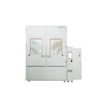
QS-DT-CSP step in type dust proof test lab
2024/3/13
![]()
Applicable standards
IEC 60629,IPXX5/X6
GB/T 4208,IPX5/X6
ISO 20653,IP5X/6X
GB/T 30038,IPX5/X6
IEC 60068-2-68,La2
GB/T 2423.37,La2
IEC 60598,IPX5/X6
GB 7000.1,IPXX5/X6
GB/T 10485,Dustproof test
IEC 60034-5,IPX5/X6
GB/T 4942.1,IPX5/X6
SAE J 575, Dust Exposure Test
Specificities
|
· The inner liner of the test chamber is made of high-quality, corrosion-resistant stainless steel. |
|
System design and description
![]()
l The blower is used to realize the circulation of talcum powder in the box.
l The blower is controlled by a frequency converter, and different air speeds can be realized by setting different frequencies.
l The dust entering the blower is pre-screened, and a vibrator is used to vibrate the dust scattered on the walls of the chamber to the screen.
l According to the test requirements into the appropriate amount of dust, not more than 4kg
l The equipment is equipped with a sample pumping system, when you need to use the sample in the box and the pumping interface connected to the negative pressure can be.
l The pumping system consists of vacuum pump, dust filter, differential pressure sensor, air flow meter, flow regulating valve and so on.
l After calculating the pumping flow according to the test requirements, the flow regulating valve is adjusted to achieve the required flow.
l There is a heating plate attached to the wall of the box, which can increase the temperature of the box through heating to reduce the humidity inside the box.
l There is a temperature and humidity integrated sensor installed in the box to collect the temperature and relative humidity inside the box.
l Test Space
① Sand and dust funnel
② Blower outlet
③ Temperature and humidity sensor
④ Exhaust port
⑤ Lighting
Control panel
Electric cabinet
① The main signals and alarm triggers of the equipment are displayed, such as gas source pressure, phase sequence of power supply and door signal.
② test chamber set temperature, real-time temperature and real-time humidity curve display
③ Digital display of test chamber set temperature, real-time temperature, real-time humidity and wind speed.
③ Digital display of test chamber set temperature, real-time temperature, real-time humidity and wind speed ④ Display of operation mode, relative pressure and flow rate of vacuum circuit
⑤ Timing display of vibration cycle and dust blowing cycle.
⑥ Display of test progress
⑦ Equipment operation information prompts
⑧ Protective operation and stop touch keys, each operation needs to be confirmed.
①Test Chamber Temperature Setting
② Operation mode selection: C1/C2/C3
③ Wind speed setting: max. 25m/s
④ Test total time setting, maximum value 99999 hours
⑤ Vibration cycle and time setting
⑥ Dust blowing cycle time setting
⑦ If equipped with serial port communication, you can set the communication baud rate and node number.
⑧ Each parameter modification needs to be saved before taking effect.
![]()
![]()
![]()
System setup and operation
![]()
![]()
Design and technical parameters
![]()
![]()
1 Other sizes and quantities can be customized
Equipment Size and Installation
|
|
|
Shanghai Acutech Automation Testing Technology Co., Ltd. Copyright 沪ICP备18019040号-1 {Disclaimer}

